Saturday, July 18, 2015

FabricPath basics

Ever thought we will have alternate to STP? If not, then you must realize that now we do have  an option,The Fabric path.As of now, it works on Cisco Nexus series of switches.

So what is fabric Path? Here i am going to explain the basics level of Fabric Path in one shot. I am sure, you would not even need to read it twice to understand the fabric Path. Lets get started...

So what is the need of FabricPath?

As, i said its kind of alternate to STP but its a lot more than that. As we all know that STP blocks the redundant links in a network. We can somehow use those redundant links using vPC, VSS, port-channel etc but still there are restrictions
-like you cant have port-channel between links going to multiple hardware without vpc/vss.
-vpc/vss also supports upto 2 hardware in peer.
-what if i want to create random topologies or just kind of plug n play topology without any hassle of STP considerations?
-what if i want to use equal cost multipathing over layer 2 links like we do in routing?

Thats where Fabric path comes in and resolve all such issues...You will see a lot more benefits when you will go through its implementation...I will start with config first and then will explain the technology and trust me, you will enjoy!!


So, how do we configure two classical ethernet switch together...

SWitch(config)#interface ethernet1/1
SWitch(config)#switchport mode trunk

So, cisco kept FabricPath configuration also very similar, You just have to just replace mode "Trunk" with mode "fabricpath"
Nexus(config)# int e1/1
N7K-1(config-if)# switchport mode fabricpath


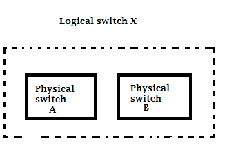
FabricPath runs over Nexus series of switches only, so what if a Nexus switch is connected to a classical Ethernet switch.hmm..so, to make it easy, few terminology were introduced to identify whether its a FabricPath Edge(which connects to classical ethernet) switch or end host, or its a Spine switch(which connects to another FP switch). The port which connects FabricPath to FabricPath switch is called FabricPath Core port.

when any vlan traffic has to be forwarded through FabricPath links, it has be specified as fabricPath vlan on all FabricPath enabled switches..

Nexus(config)#vlan 50
Nexus(config-vlan)# mode fabricpath

IMportant to note that Only FabricPath-mode VLANs are carried over FabricPath interfaces.

End host connects to a switch in normal access mode and when that data is transferred from one switch to another, that goes from edge to Fabric Path core ports.
Now, take a minute to understand this basic diagram:


Now, to understand how a frame is forwarded from one source to destination,think of normal classical ethernet frame flow. Lets say PC1 is connected on switchA and PC2 is connected on Switch D, so in a classical ethernet environment, it will just check from which port destination MAC address is being learnt and frame will be forwarded to that port and this process will continue upto destination switch. But in FabricPath, when a switch receives a Ethernet Frame on a VLAN which is fabricpath vlan, the switch will not check from which port the destination MAC is reachable, instead it will check on which Edge switch destination is connected (we will see how). Yes, so switch A will come to know that it has to forward frame to SWITCH D and it will try to find a best path to route that packet to SWITCH D. Can you believe it. A switch will forward frame based on best path to a destination switch. So, if we talk about a normal routing protocol, you need a IP address of the destination router to route the packet to that device. Similarly, in FabricPath, a new terminology was introduced which is called "Switch ID". Every switch will have a unique switch ID and source switch will forward frame to destination SwitchID based on best path available. The intermediate switch do not need to know the destination MAC address of the PC, they will just forward that frame towards destination Edge SWITCH ID.

So, now the next question comes into your mind that how it will calculate best path at layer 2? dont we need some kind of routing to let everyone know that which switch ID exists where? Yes, valid questions..

To solve this, FabricPath uses link-state "IS-IS" protocol in background to build its control plane. Using IS-IS, it builds its SWitch ID table, and from that table, it can identify the best path to reach to destination switch ID and above that, if there are multiple equal cost path, it can load balance also. I hope this makes sense now.


Now, lets take a look how MAC Learning works in FabricPath environment:

In classical ethernet, when a frame is received on a switch port, switch may or may not know the Destination but it will learn the source MAC address unconditionally,right? but in case of FabricPath, switch will not learn the MAC address until Destination is already known. that means if a destination MAC address exists in the mac table, then only source will be learnt. The idea is to keep the entries in MAC table for only those devices which are actively communicating. I mean, in a traditional ethernet, MAC entries are learnt whether there is any communication going on or not,  even a end host graciously announcing its ARP or due to any other reason and every switch who is part of that vlan will have those mac entries. This will keep on filling mac table. but in case of fabricPath, switch will not learn MAC address until destination is known. This is called "Conversational MAC Learning". (one more new term  ;-) )

Important to note that this difference is not Valid for Entire switch, but its valid for whether the fame is received on FabricPath Core PORT.
If a frame is Ingress from Edge port, the traditional source mac address is learnt but if the frame is Ingress on FabricPath Core Port (mean coming from another FP switch), then the switch will not learn source MAC address until the destination is already in mac table (conversational learning)

Example: (diagram above)

PC1 wants to send a frame to PC2 (both are in same vlan).First time communication, so it will send ARP request. As frame is ingress on Edge port, switch will learn the source mac address and its port(traditional MAC learning). Destination is broadcast (ffff.ffff.ffff)
SwitchA has multiple paths to all switches. As this is a broadcast frame, switch has to make sure it reaches all switches without creating a loop. So, to achieve the same, FabricPath introduces a concept of multi-destination tree. Means, switch has multiple path to all switches and if it has to chose one path, then create a loop free tree (Yes, at this point, it sounds like spanning tree but confusion will be cleared when you read it to advance level).
so,as of now, lets say Switch A could create below trees)


Now lets say switch A, selects one of the tree (the green one) and forwards the packet out on FabricPath port. Obviously it has to encapsulate the frame into FabricPath header. (Read here for the complete encapsulation method).

SwtichB will receive the frame, It is also part of green tree, so it will forward the frame on all FP port except, it was received on.

SwitchD receive the frame. It knows, it is an edge switch because it has end machine connected, means it has access-port which is part of fabricPath vlan. So, it decapsulates the packet and see that the frame is broadcase for vlan10. so, it will forward the frame in all ports in vlan10 but IT WILL NOT LEARN SOURCE MAC ADDRESS, because the frame was ingress on FP port and destination (ffff.ffff.ffff) is not known, so source will not be learnt.

Now, the ARP response from PC2 will be unicast, SWitch D will learn the source MAC because frame is ingress on CE port, frame will be forwarded on one of the tree, now when Switch A receives the frame, it knows the Destination MAC which it learnt from ARP request when PC1 sent the first packet. So, for a ARP reply packet from Pc2 to PC1, now destination is known to SWitchA, so it will learn the source MAC address but what it will not create an entry that source mac (PC2 mac) is being learnt via port E1/1, but instead it will learn tht PC1 MAC adress is learnt via SwitchD. (That is conversationl MAC learning). Next frame destined for PC2, will be forwarded by SwitchA based on the entry that it created that says "PC2 is reachable via SwitchD". so all intermediate switch will forward that frame to switch D, instead of learning mac address for every single host.


I hope the basic of FabricPath is clear from this post. The unanswered question like below will explain in next simplified post.
1)How did SwitchA select which tree to use and how frame is forwarded within a tree?
2)what if there are multiple path and want to do load balancing in fabricPath?
2)How FabricPath encapsulation works?
3)Configuration and verification of FabricPath.
4)Switch ID allocation?
5)how switch ID table is created and frame is forwarded at each switch.
6)Post in comments if you have any question so far.

Thank you!!

Tuesday, May 13, 2014

Nexus Line Cards Naming Convention

This post is a brief explaination about knowing the specification of Nexus series switches M and F series line modules ( or I/O modules) from its name
.
I am taking example of F-Series I/O module (N7K-F248XP-25) and similarly M series can also b read.
Example:
N7K-F2 48 X  P - 2  5 

Below is the explanation of each field and explained with other option you may see in different line cards:
N7k
is self explanatory, it indicates the type of chassis,
F2 
it is the series, family or generation of F series line cards. This one is 2nd generation, means F2 family. Similarly M1, M2, F3 and so on.
48
No. of ports on the card.

X   Or  F or C  or
G means ports are 1 Gig ports
X means 10 Gig ports
F means 40 Gig ports (Ex: N7K-F312FQ-25).
C indicates 100 G (Ex: N77-F312CK-26)

P  or S or  T or Q or Kor 2
it is interface type,
S means SFP
P means SFP+ .
T means RJ45(Ex: N7K-F248XT-25E)
Q means QSFP+(Ex: N7K-F312FQ-25) ,
K means Cisco CPAK( Ex: N77-F312CK-26)
2  means X2 (ex. N7K-M108X2-12L)

25 
Means FAB2 module required and 5 FAB2 module needs to be installed to run at full capacity.

Monday, April 14, 2014

Nexus 5548P vs 5548UP vs 5596UP Switch

I am often asked what is difference between Nexus 5548P and 5548UP switch? In this post i am going to explain the differences between these two and will also include 5596UP into the discussion.

First of all, all these 3 models are Nexus 5k Switches and basically 5500 series models.
"U" stands for "Unified" ports, so what does that "unified port" mean? Unified means a port is capable of running into either "Ethernet" or "FC" (Fibre Channel).

For those who are not aware of SAN protocols, i would like to inform you that term "Fibre" here does not mean the "Fiber" Media ( ie. copper vs fiber) which people refer in terms of cable, [ please note the difference in spelling, Fibre vs Fiber).

Fibre Channel or FC is a protocol stack in SAN, similar to what TCP/IP is to Networks. SAN switches run on FC protocol standards, not Ethernet or TCP/IP.(Just a highlevel overview)

So coming back to 5500 series models, all ports of 5548UP and 5596UP models of  Nexus 5k, can be used in ether Ethernet or FC mode,however, ports on 5548P do not work in FC mode. But the ****important thing to note is that this difference is valid for "In-built fixed" ports only******. That means, both 5548P and 5548UP switch comes with 32-port "in-built"or Fixed ports, plus one expansion module capable of 16 ports.

So, basicaly 5548P support Unified Port (Ethernet or native FC ) on the expansion module only,however, in 5548UP, all ports are unified ports.

5596UP comes with built-in 48 Ports, plus we can use  3 expansion slots for additional ports depending on our requirement.

That was the main difference, other differences are:
- 5548P and UP switch are 1 RU,however, 5596 is 2 RU switch
-Switching capacity of 5548 series are 960Gbps ,however, 5596 is 1.92 Tbps
-5548P only supports front-back airflow,however, 5548UP and 5596 supports both front-back and back-front.
-a Seperate Layer 3 Daughter card can also be ordered/used to get 160 Gbps of Layer 3 routing capability in 5548P and 5548UP switches, however, 5596UP can support L3 routing engine through an Expansion Module.

Wednesday, January 29, 2014

Basic understanding of OTV

Today i am going to help you understand Why we need OTV?

Lets say, we have 3 switches (A,B,C). Switch A is connectec to B and Switch B is connected to Switch C. and Switch A has 2 vlans created on it, vlan 10 and 20. What if we want the the vlan 10 and 20 to be extended to Switch C over Switch B, We will have to simply create vlan 10 and 20 on both switch B and C and allow both the vlans on trunks connecting the switches, right? and its simple!!

If you look at this pic, we have two Datacenters, DC1 and DC2 which are geographicaly far away from each other, lets say one in Newyork and another one in Los Angles and  there are some server which are there in both data centers,however, they sync their hearbeat over layer 2 only and doesnt work on layer 3. So,we have a requirment that we have to extend vlan 10 and 20 from DC1 to another data center, DC2!! You may call it Datacenter Interconnect (DCI).


can we do the same thing which we did to extend vlan from switch A to switch C in above example? Ofcourse Not!!, so what the are the solutions to achieve this?
Until OTV came into picture, we had few of the below options to achieve this:
-VPLS
-Dark Fiber (CWDM or DWDM)
-AToM
-L2TPv3
 
These are the services provided by Service Providers and they work on different mechanisms but basicaly what they do is, they provide you a layer 2 path between DC1 to DC2 similar to a trunk link between Switch A and Switch B. So what does that mean? If a broadcast is sent or a ARP request is sent, that will travel across the service provider to another data center in that VLAN? Ofcourse YES!! Your STP domain will also get extended over DCI. So, if a device in vlan 10 in DC1 is trying to communicate with another device which is also in DC1 but the ARP request will go all the way to DC2 switches on which that particular vlan is configured. 

So, to avoid such problems, Cisco introduced OTV  (Overlay Transport Virtualization) which is basicaly a DCI (data center interconnect) technology to be configured on Nexus Switches. Using OTV, we can extend Layer 2 between two or more datacenters over traditional L3 infrastructure provided by Service Provider, and we dont need a seperate L2 link for layer 2 extension and we will still be able to limit STP domain and unnecessary broadcast over WAN links.  It can overlay multiple VLAN with a simple design. Basically what it does is that, Datacenters will be able to advertise their MAC addresses to each other(its called
Mac in IP" routing) and a decision can be made on the basis of MAC addresses whether that MAC address is local or in another data center and based on that, frame can be forwarded or limited to a particular data center only. OTV uses a control protocol to map MAC address destinations to IP next hops that are reachable through the normal L3 network core.
So, in Cisco's language "OTV can be thought of as MAC routing in which the destination is a MAC address, the next hop is an IP address, and traffic is encapsulated in IP so it can simply be carried to its MAC routing next hop over the core IP network. Thus a flow between source and destination host MAC addresses is translated in the overlay into an IP flow between the source and destination IP addresses of the relevant edge devices. This process is called encapsulation rather than tunneling as the encapsulation is imposed dynamically and tunnels are not maintained"


How this is implemented, that i will show in another simplified post!!Thank you!!

Friday, June 28, 2013

Cisco Nexus 7k, 5k, 2k FAQ

Nexus FAQ's :

Q. What are the differences between M and F series line cards? What are the differences in F1, F2, F2e and F3 cards?
A. The initial series of line cards launched by cisco for Nexus 7k series switches were M1 and F1. M1 series line cards are basicaly used for all major layer 3 operations like MPLS, OTV, routing etc,however, the F1 series line cards are basically layer 2 cards and used for for FEX, FabricPath, FCoE etc. If there is only F1 card in your chassis, then you can not achieve layer 3 routing. You need to have a M1 card installed in chassis so that F1 card can send the traffic to M1 card for proxy routing. The fabric capacity of M1 line card is 80 Gbps. Since F1 line card dont have L3 functionality, that means you can not use same interface in L3 mode. They are  provide a fabric capacity of 230 Gbps.
Later cisco released M2 and F2 series of line cards. A F2 series line card can also do basic Layer 3 functions means you can use interface in L3 mode,however,can not be used for advance L3 feature like OTV or MPLS. M2 line card's fabric capacity is 240 Gbps while F2 series line cards have fabric capacity of 480 Gbps.
The problem with F2 card is that they can not be installed in same vdc with any other card.F2 card has to be in its own vdc.
So, to resolve that, Cisco introduced F2E line cards which can be used  with other M series line cards in same VDC. It supports layer 3 but if it is alone in a single vdc. If it is being used with another card,  it supports (unlike F2) but then it can be used in L2 mode only.
So, finaly cisco launched F3 cards which are full L3 card. Support all advance layer 3 feature like otv, mpls etc. can be mixed with other cards in same vdc in L2 or L3 mode.

Q. What is Fabric Module? Is it same as line cards?
A. Fabric module are the hardware modules which provides backplane connectivity between I/O modules and SUP. In traditional switches like 6500, the crossbar switch fabric was integrated into chassis and there was no redundancy if crossbar switch fabric is faulty,however, in nexus 7k we have fabric redundancy using switch fabric module.
They are inserted into chassis in the backside and are hot-swappable same as line cards (I/O) modules,however, they dont have any ports on them to connect any external device. So they are not alternatives to line card or I/O modules.  You can see them in "show module" command output and they are shown as "X-bar". Nexus 7010 and 7018 can have upto 5 fab modules.

Q. What is fabric module capacity?
A. There are two series of Fabric modules, FAB1 and FAB2.
Each FAB1 has a maximum throughput of 46Gbps per slot meaning the total per slot bandwidth available when chassis is running on full capacity, ie. there are five FAB1s in a single chassis would be 230Gbps.  Each FAB2 has a maximum throughput of 110Gbps/slot meaning the total per slot bandwidth available when there are five  FAB2s in a single chassis would be 550Gbps.  These are the FAB module capacity,however, the actual throughput from a line card is really dependent on  type of line card being used and the fabric connection of the linecard being used.

Q. Does a Nexus 2k has an operating system (OS)?
A. No, nexus 2k or fex is a dumb device. It doesnt have any PRE-INSTALLED operating system on it. It can be used with its parent Nexus 5k or 7k switch. When connected to its parent switch, it downloads the operating system from parent switch only.

Q. What is difference between shared mode vs dedicated mode
A. explained in : Shared vs Dedicated mode of ports in Nexus 7k

Q. Can we connect a Nexus 2k to Nexus 7k?
A. Yes,however, not on every line card. There are few line cards which supports Fex.

Q. Can we connect a Nexus 2k or FEX to two parent switches or it can be controlled or connected by only one switch?
A. Yes, we can connect a fex to two parent switches,however, only 5ks. we CANNOT connect a nexus 2k to two Nexus 7Ks. This is dual-homed FEX design and it is supported.

Q. Can we mix different cards like M1/M2/F1/F2 in same vdc?
A. You can mix all cards in same vdc EXCEPT F2 card. The F2 card has to be on it's own VDC.  You can't mix F2 cards with M1/M2 and F1 in the same VDC. As per cisco, its a hardware limitation and it creates forwarding issues.

Q. Can we do a redistribute in ospf without a route-map?
A. No, a route-map is required in NX-os while redistributing.

Q. What are the differences between VPC and VSS
A. Explained in: VSS vs VPC (difference between VSS and vPC)

Q. What is VDC
A. Explained in detail: VDC Overview

Q. Can a device in one VDC communicate with device in another VDC?
A. One VDC can not communicate to another VDC over backplane. If a reachability is needed, then we need add a physical connection (via a direct cable or through another switch) between the ports in two seperate VDC's.

Q. Can 3 or more Nexus 7K or 5Ks become vPC Peers?
A. No,you can have only two devices as vPC peers. Each device can serve as a vPC peer to only one other vPC peer.

Q. What are the difference between vPC-peer link and vPC keep-alive link?
A. vPC-peer link is a layer 2 link that is used to check the consistancy parameters,states and config sync and traffic flow(in some cases only). vpc keep-alive link is L3 reachability which is used to check the peer status and role negotiation. Role negotiation happens at the initial stage only. vpc keep-alive link must be setup first in order to bring vpc up.  vPC peer link will not come up unless the peer-keepalive link is already up and running.

Q. What are the vpc keep-alive link timers?
A. The default interval time for the vPC peer-keepalive message is 1 second. This is configurable between 400 milliseconds and 10 seconds.You can configure a hold-timeout value with a range of 3 to 10 seconds; the default hold-timeout value is 3 seconds.

Q. How many VDC’s can the Nexus 7000 support?
A. It depends on which SUP you are using:
4 VDCs  with SUP1,
4+1 (1 VDC for management) SUP2;
8 + 1 (management) VDC’s with SUP2E.

Q. On a Nexus 7k, when trying to perform a 'no shut' on Ethernet 1/3,the ERROR: Ethernet1/3: Config not allowed, as first port in the port-grp is dedicated error message is received.

A. Explained in details: Shared vs Dedicated mode of ports in Nexus 7k


Tuesday, June 18, 2013

Shared vs Dedicated mode of ports in Nexus 7k

Hi..have you ever seen this error message while trying to configure a port?

"ERROR: Ethernet1/4: Config not allowed, as first port in the port−grp is dedicated"

To understand this, we need to understand what is port-group? Below is the image of N7K-M132XP-12 ine card. This line card has 32 ports and all are 10 Gig port. So what does that mean? Does it mean thate ach one of them is a 10 Gig port and we can have all of these 32 ports connected at the same time and we should be able to get 320 Gbps speed? Not exactly...!!
Yes, they are 10 Gig ports,HOWEVER, that 10 Gig is shared among 4 ports in a group. That group is basically all the ports on same hardware ASIC.


Now take a closer look:
As per the below pic, you can see that even or odd continuous ports are on one side and each group of four ports are on same hardware ASIC. This is a port-group and first port of the group is marked YELLOW as you can see in below diagram.


So, being said that N7K-M132XP-12 has 32 10G ports, it means that each port-group (group of 4 ports for this line card) share 10G speed among themselves. YES!! that is correct. All ports dont get 10G dedicated bandwidth. So, the total capacity of the card is 80G, not 320 (as we were expecting) as there can be 8 port-grp of 4 ports each. This is designed on the concept that "Chances are less that all devices are sending data at the same time". So, 1,3,5,7 will be in same port-grp and similary 2,4,6,8 and so on...!!

So, 4 ports in a group will share the total available bandwidth of 10G. 
What if we have requirement for some critical application that we need dedicated bandwidth of 10 G? In that case, first port of a port-group can be put into "DEDICATED" mode and that port will always be the first one of the group..ie. marked in yellow as shown in above pic. So, 1,2,9,10,17,18,25,26 can be put into dedicated mode and if you have put a port in a port-grp into dedicated mode, all other 3 ports in that group will get disabled. You can not configure them. If you have put Eth1/2 into dedicated mode, and if you try to configure Eth1/4 then you will get : "ERROR: Ethernet1/4: Config not allowed, as first port in the port−grp is dedicated"

Shared mode is the default mode. Command to configure port into dedicated mode is:
We first need to shutdown the port
N7K# config t
N7K(config)#interface Eth1/2
N7K(config-if)#rate-mode dedicated


Monday, June 17, 2013

Fex Identity-Mismatch (identity-mismatch error on nexus 5k)

While checking fex links, we got the " Identity-Mismatch" error as shown below in "sh int fex" output:

Nexus-5k-1# sh int fex-fabric 
     Fabric      Fabric       Fex                FEX           
Fex  Port      Port State    Uplink    Model         Serial    
---------------------------------------------------------------
103   Eth1/17        Active     1    N2K-C2248TP-1GE  JAX1122AAA
103   Eth1/18        Active     2    N2K-C2248TP-1GE  JAX1122AAA
103   Eth1/19        Active     3    N2K-C2248TP-1GE  JAX1122AAA
103   Eth1/20        Active     4    N2K-C2248TP-1GE  JAX1122AAA
105   Eth1/23        Active     1    N2K-C2248TP-1GE  MLX1122BBB
105   Eth1/24        Active     2    N2K-C2248TP-1GE  MLX1122BBB
105   Eth1/25  Identity-Mismatch     4    N2K-C2248TP-1GE  PQR3344DDD  <<<Notice this
105   Eth1/26        Active     4    N2K-C2248TP-1GE  MLX1122BBB


Nexus-5k-2# sh int fex-fabric 
     Fabric      Fabric       Fex                FEX           
Fex  Port      Port State    Uplink    Model         Serial    
---------------------------------------------------------------
102   Eth1/17        Active     1    N2K-C2248TP-1GE  LMN2244CCC
102   Eth1/18        Active     2    N2K-C2248TP-1GE  LMN2244CCC
102   Eth1/19        Active     3    N2K-C2248TP-1GE  LMN2244CCC
102   Eth1/20        Active     4    N2K-C2248TP-1GE  LMN2244CCC
104   Eth1/23        Active     1    N2K-C2248TP-1GE  PQR3344DDD
104   Eth1/24        Active     2    N2K-C2248TP-1GE  PQR3344DDD
104   Eth1/25        Active     3    N2K-C2248TP-1GE  PQR3344DDD
104   Eth1/26  Identity-Mismatch     3    N2K-C2248TP-1GE  MLX1122BBB  <<<Notice this

Basically this error is related to incorrect cabling..
As we know that a nexus 2k switch or FEX is connected to its parent Nexus 5k over fex links.
One Fex (2k) can be dual homed to two Nexus 5k switches. and when a nexus 2k is connected to Nexus 5k, a unique fex associate number is assigned to that particular 2k to identify it uniquely. 

So, i had four nexus 2k switches whose serial numbers are JAX1122AAA,MLX1122BBB, PQR3344DDD and LMN2244CCC.   JAX1122AAA and ,MLX1122BBB are FEX switches for Nexus5k1. and  PQR3344DDD and LMN2244CCC are part of Nexus-5k-2.  JAX1122AAA has been given FEX associate number 103 and MLX1122BBB has been given 105,LMN2244CCC is assigned 102  and PQR3344DDD is assigned 104. Each fex is connected to its parent switch via 4 fex links.

Idealy, all 4 fex links which are under same FEX ASSOCIATE NUMBER should be going to same 2k,however, one of our onsite engineer incorrectly cabled one of the fex link from 103 on Nexus-5k-1 to another 2k which was part of FEX number 104 on Nexus-5k-2 and we started getting identity mismatch. As you can see in above output,under FEX 105 on Nexus-5k-1, the Eth1/25 is showing PQR3344DDD serial number,however, all other interfaces showing MLX1122BBB and vice versa on Nexus-5k-2 for Eth1/26.

In order to verify cabling and make sure right fex or 2k is connected to correct parent 5k switch with respective to its FEX associate number, we can use "show interface fex-fabric" command and verify the same using serial number that all are correct switches.
once the cable were swapped, we started getting right serial number for Eth1/25. 


Nexus-5k-1# sh int fex-fabric 
     Fabric      Fabric       Fex                FEX           
Fex  Port      Port State    Uplink    Model         Serial    
---------------------------------------------------------------
103   Eth1/17        Active     1    N2K-C2248TP-1GE  JAX1122AAA
103   Eth1/18        Active     2    N2K-C2248TP-1GE  JAX1122AAA
103   Eth1/19        Active     3    N2K-C2248TP-1GE  JAX1122AAA
103   Eth1/20        Active     4    N2K-C2248TP-1GE  JAX1122AAA
105   Eth1/23        Active     1    N2K-C2248TP-1GE  MLX1122BBB
105   Eth1/24        Active     2    N2K-C2248TP-1GE  MLX1122BBB
105   Eth1/25       Active      3    N2K-C2248TP-1GE  MLX1122BBB  ---->>>>Correct now
105   Eth1/26        Active     4    N2K-C2248TP-1GE  MLX1122BBB

Sunday, June 16, 2013

VSS vs VPC (difference between VSS and vPC)

I know many of you have been looking for an answer to this question "what are the differences between VSS and vPC? "..here are the differences  between VPC and VSS in a very easy way, You just need to read it once..

Both are used basically to support multi-chassis ether-channel that means we can create a port-channel whose one end is device A,however, another end is physically connected to 2 different physical switches which logically appears to be one switch.

There are certain differences as listed below:

-vPC is Nexus switch specific feature,however,VSS is created using 6500 series switches

-Once switches are configured in VSS, they get merged logicaly and become one logical switch from control plane point of view that means single control plane is controlling both the switches in active standby manner  ,however, when we put nexus switches into vPC, their control plane are still separate. Both devices are controlled individually by their respective SUP and they are loosely coupled with each other.


-In VSS, only one logical switch has be managed from management and configuration point of view. That means, when the switches are put into VSS, now, there is only one IP which is used to access the switch. They are not managed as separate switches and all configuration are done on active switch. They are managed similar to what we do in stack in 3750 switches,however, in vPC, the switches are managed separately. That means both switches will have separate IP by which they can be accessed,monitored and managed. Virtually they will appear a single logical switch from port-channel point of view only to downstream devices.
-As i said, VSS is single management and single configuration, we can not use them for HSRP active and standby purpose because they are no longer 2 seperate boxes. Infact HSRP is not needed, right?
one single IP can be given to L3 interface and that can be used as gateway for the devices in that particular vlan and we will still have redundancy as being same ip assigned on a group of 2 switches. If one switch fails, another can take over.,however, in vPC as i mentioned above devices are separately configured and managed, we need to configure gateway redundancy same as in traditional manner.

For example: We have 2 switches in above diagram. Switch A and B, when we put them in VSS, they will be accessed by a single logical name say X and if all are Gig ports then interfaces will be seen as GigA\0\1, GigA\0\2....GigB\0\1,GigB\0\2 and so on...
however,if these are configured in vPC, then they will NOT be accessed with single logical name. They will be accessed/managed separately. Means, switch A will have its own port only and so on B.

-Similary, in VSS same instances of stp,fhrp,igp,bgp etc will be used,however, in vPC there will be separate control plane instances for stp,fhrp,igp,bgp just like they are being used in two different switches

-in VSS, the switches are always primary and secondary in all aspects and one switch will work as active and another as standby,however, in vPC they will be elected as primary and secondary from virtual port-channel point of view and for all other things,they work individualy and their role of being primary/secondary regarding vpc is also not  true active standby scenario,however, it is for some particular failure situation only. For example, if peer-link goes down in vpc, then only secondary switch will act and bring down vpc for all its member ports.

-VSS can support L3 port-channels across multiple chassis,however, vpc is used for L2 port-channels only.

-VSS supports both PAgP and LACP,however, VPC only supports LACP.

-In VSS, Control messages and Data frames flow between active and standby via VSL,however, in VPC,Control messages are carried by CFS over Peer Link and a Peer keepalive link is used to check heartbeats and detect dual-active condition.

I hope this was helpful. I will keep adding more as i experience more.Thank you!!


Tuesday, June 11, 2013

Virtual Device Context (vdc) Overview and Configuration example

Below is the very basic explanation of cisco vdc and i hope you will be able to understand by reading it once only

Cisco's virtual device context or vdc is basically a concept of dividing a single Nexus 7000 hardware box into multiple logical boxes in such a way that they look like different physical device to a remote user/operator and each of the provisioned logical devices is configured and managed as if it were a separate physical device.
For example, you have a data center where you have deployed Nexus 7k in datacenter. Now, there are few other companies who don't have enough money to expend in setting up Nexus 7000 so they come to you to host a data center for them. You can simply virtualize your nexus 7000 into multiple virtual switches and can assign one logical portion(that is called vdc)  to one company. When they will login to their logical switch (looks like a separate physical switch to user) they can do whatever they want, other logical partition i.e. other vdc will remain unaffected. You can create vlans with same name/number in all vdc's and they will not interfere with each other. A particular vdc operator will not even come to know that same switch is being used by multiple user virtually. Only Admin can create/delete vdc's and from Admin vdc only, we can see other vdcs.

Similary, vdc can be used to create different test and production traffic. In my previous project, we created one vdc for test environment in order to test new implementation/protocol etc and another vdc for production traffic. If our test used to successful in our test environment, then only we used to put them into production.

How many vdc we can create?? hmm...it depends which supervisor engine you are using.
-If you are using SUP1, then you can create upto 4 vdc's. All of them can be used to carry data traffic and you can create/delete vdcs from default vdc which can also be used for data traffic.
-if you are using SUP2, then you can create 1 admin + 4 data vdc. That means, you can not use admin vdc for data traffic. That will be used for only admin purpose i.e. managing other vdc's.
-if you are using SUP2E, then you can create 1+8 vdc, where 1 admin plus 8 production vdc.

Within VDC it can contain its own unique and independent set of VLANs and VRFs. Each VDC can have assigned to it physical ports, thus allowing for the hardware data plane to be virtualized as well. Within each VDC, a separate management domain can manage the VDC itself, thus allowing the management plane itself to also be virtualized.

physical interfaces cannot be shared by multiple VDCs. This one-to-one assignment of physical interfaces to VDCs is at the basis of complete isolation among the configured contexts. However, there are two exceptions:
• The out-of-band management interface (mgmt0) can be used to manage all VDCs. Each VDC has its own representation for mgmt0 with a unique IP address that can be used to send syslog, SNMP and other management information.
• When a storage VDC is configured, a physical interface can belong to one VDC for Ethernet traffic and to the storage VDC for FCoE traffic. Traffic entering the shared port is sent to the appropriate VDC according to the frame's EtherType. Specifically, the storage VDC will get the traffic with EtherType 0x8914 for FCoE Initialization Protocol (FIP) and 0x8906 for FCoE.
Physical interfaces can be assigned to a VDC with a high degree of freedom. However, there are differences among different I/O modules because of the way the VDC feature is enforced at the hardware level. The easy way to learn the specific capabilities of the installed hardware is by entering the show interface x/y capabilities command to see the port group associated with a particular interface.


Switch Resources that Can Be Allocated to a VDC:
Physical Interfaces, PortChannels, Bridge Domains and VLANs, HSRP and GLBP Group IDs, and SPAN
Switch Resources that Cannot Be Allocated to a VDC:
CPU*, Memory*, TCAM Resources such as the FIB, QoS, and Security ACLs
  * Future releases may allow allocation of CPU or memory to a VDC.

VDC configuration is so easy. 

step 1   Log in to the default VDC with a username that has the network-admin role.
Step 2   Enter configuration mode and create the VDC using the default settings.
N7k# configure terminal
N7k(config)# vdc WDECAIB
Note:  Creating VDC, one moment please ...
switch(config-vdc)#
                
Step 3   (Optional) Allocate interfaces to the VDC.
N7k(config-vdc)# allocate interface ethernet 1/1-8

similarly more interfaces can be assigned. below is the screenshot of a vdc configuration.
Initially, all physical interfaces belong to the default VDC (VDC 1). When you create a new VDC, the Cisco NX-OS software creates the virtualized services for the VDC without allocating any physical interfaces to it. After you create a new VDC, you can allocate a set of physical interfaces from the default VDC to the new VDC.


The interface allocation is the most important part of vdc configuration. You can not assign ports of same port-group to different vdc.If you are unable to assign any interface to particular vdc or some ports are being automatically being assigned, then it could be port-grouping issue. Port group is basicaly how many parts are on same hardware ASIC. So, if 4 ports are on same ASIC, then they all must be in same vdc as they are sharing and being operated by same asic.  How many port-groups are there in my card or is there a fix formula? Basically it depends which type of I/O module card we are using. for example:

•N7K-M202CF-22L (1 interface x 2 port groups = 2 interfaces 100G modules)—There are no restrictions on the interface allocation between VDCs.

•N7K-M206FQ-23L (1 interface x 6 port groups = 6 interfaces 40G modules)—There are no restrictions on the interface allocation between VDCs.

•N7K-M224XP-23L (1 interface x 24 port groups = 24 interfaces 10G modules)—There are no restrictions on the interface allocation between VDCs.

•N7K-M108X2-12L (1 interface x 8 port groups = 8 interfaces)—There are no restrictions on the interface allocation between VDCs.

•N7K-M148GS-11L, N7K-M148GT-11, and N7K-M148GS-11 (12 interfaces x 4 port groups = 48 interfaces)—There are no restrictions on the interface allocation between VDCs, but we recommend that interfaces that belong to the same port group be in a single VDC.

•N7K-M132XP-12 (4 interfaces x 8 port groups = 32 interfaces)—Interfaces belonging to the same port group must belong to the same VDC. See the example for this module in Figure 1-3.

•N7K-M148GT-11L (same as non-L M148) (1 interface x 48 port groups = 48 interfaces)—There are no restrictions on the interface allocation between VDCs.

•N7K-M132XP-12L (same as non-L M132) (1 interface x 8 port groups = 8 interfaces)—All M132 cards require allocation in groups of 4 ports and you can configure 8 port groups.


================
Switching between VDC's

If you have logged into default VDC, you can use “Show VDC” command to see what all other vdc’s have been created.


IF you want to switch to any other vdc from default vdc, you can use “switchto vdc <vdc name>” command as shown below and if you have logged into user created vdc WDECAIB  from default vdc using switchto command, you can use “switchback” command to come back to default vdc, however, if you have directly ssh/telnet into user created vdc WDECAIB  here, you can not do a “switchback” to come into default vdc.

I hope it was helpful. You can read through my blog to know more about vdc's like vdc users etc.


Wednesday, June 5, 2013

"sh int brief" vs "sh ip int brief" in nexus 7k,5k

sh ip int brief doesn't work on Nexus series switches (7000,5000) like any other IOS based switch.
this command only shows Layer 3 interfaces that too with specific to vrf only.


for example if you have to see management vrf interface, then you need to do a " sh ip int brief vrf management"
If you do not specify any vrf, then Nexus will only show default vrf interfaces as shown below

Nexus7k# sh ip int brief
IP Interface Status for VRF "default"(1)
Interface            IP Address      Interface Status

Nexus7k# sh ip int brief vrf management
IP Interface Status for VRF "management"
Interface            IP Address      Interface Status
mgmt0                10.7.6.5        protocol-up/link-up/admin-up       

if you want to see all the interfaces for their status, then you need to do a "sh int brief" instead of "sh ip int brief".

switch# show interface brief
--------------------------------------------------------------------------------
Ethernet VLAN Type Mode Status Reason Speed Port
Interface Ch #
--------------------------------------------------------------------------------
Eth1/1 1 eth trunk up none 10G(D) 4000
Eth1/2 1 eth trunk up none 10G(D) 4000
Eth1/3 1 eth trunk up none 10G(D) 4000
Eth1/4 1 eth trunk up none 10G(D) 4000
Eth1/5 1 eth access down SFP not inserted 10G(D) --
Eth1/6 1 eth access down SFP not inserted 10G(D) --
Eth1/7 1 eth trunk up none 10G(D) 10

Monday, June 3, 2013

vPC (Virtual port-channel )

Overview
A virtual PortChannel (vPC) allows links that are physically connected to two different Cisco Nexus 7000 or 5000 Series devices to appear as a single PortChannel to a third device. The third device can be a Cisco Nexus 2000 Series Fabric Extender or a switch, server, or any other networking device. A vPC can provide Layer 2 multipathing, which allows you to create redundancy by increasing bandwidth, enabling multiple parallel paths between nodes and load-balancing traffic where alternative paths exist.
After you enable the vPC function, you create a peer keepalive link, which sends heartbeat messages between the two vPC peer devices.
The vPC domain includes both vPC peer devices, the vPC peer keepalive link, the vPC peer link, and all the PortChannels in the vPC domain connected to the downstream device. You can have only one vPC domain ID on each device.
A vPC provides the following benefits:
Allows a single device to use a PortChannel across two upstream devices
Eliminates Spanning Tree Protocol blocked ports
Provides a loop-free topology
Uses all available uplink bandwidth
Provides fast convergence if either the link or a device fails
Provides link-level resiliency
Helps ensure high availability
The vPC not only allows you to create a PortChannel from a switch or server that is dual-homed to a pair of Cisco Nexus 7000 or 5000 Series Switches, but it can also be deployed along with Cisco Nexus 2000 Series Fabric Extenders.

The following list defines critical vPC concepts:
vPC: vPC refers to the combined PortChannel between the vPC peer devices and the downstream device.
vPC peer switch: The vPC peer switch is one of a pair of switches that are connected to the special PortChannel known as the vPC peer link. One device will be selected as the primary device, and the other will be the secondary device.
vPC peer link: The vPC peer link is the link used to synchronize states between the vPC peer devices. The vPC peer link carries control traffic between two vPC switches and also multicast, broadcast data traffic. In some link failure scenarios, it also carries unicast traffic. You should have at least two 10 Gigabit Ethernet interfaces for peer links.
vPC domain: This domain includes both vPC peer devices, the vPC peer keepalive link, and all the PortChannels in the vPC connected to the downstream devices. It is also associated with the configuration mode that you must use to assign vPC global parameters.
vPC peer keepalive link: The peer keepalive link monitors the vitality of a vPC peer switch. The peer keepalive link sends periodic keepalive messages between vPC peer devices. The vPC peer keepalive link can be a management interface or switched virtual interface (SVI). No data or synchronization traffic moves over the vPC peer keepalive link; the only traffic on this link is a message that indicates that the originating switch is operating and running vPC.
vPC member port: vPC member ports are interfaces that belong to the vPCs.

vPC configuration on the Cisco Nexus 5000 Series includes these steps:
Enable the vPC feature.
Create a vPC domain and enter vpc-domain mode.
Configure the vPC peer keepalive link.
(Optional) Configure system priority.
(Optional) Configure vPC role priority.
Create the vPC peer link.
Move the PortChannel to vPC.
                        

Introduction to cisco nexus 7k, 5k and 2k switches

Nexus 7000
The Cisco Nexus Series switches are modular network switches designed for the data center. Nexus 7000 chassis includes 4, 9, 10 and 18 slot chassis, however, we have nexus 7010 deployed in data centers at Core layers.
The first chassis in the Nexus 7000 family is Nexus 7010 switch which is a 10-slot chassis with two supervisor engine slots and eight I/O module slots at the front, as well as five crossbar switch fabric modules at the rear. 

All switches in the Nexus range run the modular NX-OS firmware/operating system. The Cisco NX-OS software is a data center-class operating system built with modularity, resiliency, and serviceability at its foundation. Based on the industry-proven Cisco MDS 9000 SAN-OS software, Cisco NX-OS helps ensure continuous availability and sets the standard for mission-critical data center environments. The highly modular design of Cisco NX-OS makes zero-effect operations a reality and enables exceptional operational flexibility. 
Nexus 7010
-10 slots: 1-4 and 7-10 are line card slots, 5-6 are supervisor slots
-21 RU height
-Supports 384 10Gbit/s, and/or 1Gbit/s ports, all non-blocking ports
-9.9 Tbit/s system bandwidth
-480 Gbit/s, 720Mpps per slot
-Air flow is front to back, bottom to top
-Up to 5 Crossbar Fabric Modules
-Up to 3 power supplies

Supervisor Engine
Performs control plane and management functions
Dual-core 1.66 Ghz intel Xeon Processor with 4 GB DRAM
2 MB NVRAM, 32 GB internal bootdisk, compact flash slots
out-of-band 10/100/1000 management interface
Always-on connectivity management processor (CMP) for lights-out management
console and auxiliary serial ports.

Management Interface
10/100/1000 interface used exclusively for management
It is part of dedicated “management”vrf and can not be moved to any other or default vrf.
You can not assign other ports (Ethernet) to this vrf.
Crossbar Switch Fabric Modules 
A single Cisco Nexus 7000 chassis can be configured with one or more fabric modules, up to a maximum of five for capacity as well as redundancy. Each I/O module installed in the system will automatically connect to and use all functional installed switch fabric modules. A failure of a switch fabric module will trigger an automatic reallocation and balancing of traffic across the remaining active switch fabric modules. Replacement of the failed fabric module reverses this process. Once the replacement fabric module is inserted and online, traffic is again redistributed across all installed fabric modules, thereby restoring the redundancy level.
The Cisco Nexus 7000 Fabric Modules for the Cisco Nexus 7000 Chassis are separate fabric modules that provide parallel fabric channels to each I/O and supervisor module slot.  The fabric module provides the central switching element for fully distributed forwarding on the I/O modules.
Switch fabric scalability is made possible through the support of from one to five concurrently active fabric modules for increased performance as your needs grow. All fabric modules are connected to all module slots. The addition of each fabric module increases the bandwidth to all module slots up to the system limit of five modules. The architecture supports lossless fabric failover, with the remaining fabric modules load balancing the bandwidth to all the I/O module slots, helping ensure graceful degradation.

Two fabric generations available – Fabric 1 and Fabric 2
  

 All I/O modules compatible with both Fabric 1 and Fabric 2


Cisco Nexus 5000 Series Switches
The Cisco Nexus 5000 Series switches include a family of line-rate, low-latency, lossless 10-Gigabit Ethernet, Cisco Data Center Ethernet, Fibre Channel over Ethernet (FCoE), and native Fibre Channel switches for data center applications. The Cisco Nexus 5000 Series includes the Cisco Nexus 5500 Platform and the Cisco Nexus 5000 Platform.
Mainly Nexus 5k is used for layer 2 switching,however, it can support L2 add-in card.
-Currently there are 2 generations of 5000 series switches:
  5000 series – 5010 & 5020
  5500 series – 5548 & 5596

Cisco Nexus 5548P Switch

The Cisco Nexus 5548P Switch is the first of the Cisco Nexus 5500 platform switches. It is a one-rack-unit (1RU) 10 Gigabit Ethernet and FCoE switch offering up to 960-Gbps throughput and up to 48 ports. The switch has 32 1/10-Gbps fixed SFP+ Ethernet and FCoE ports and one expansion slot.

The Cisco Nexus 5548UP is a 1RU 10 Gigabit Ethernet, Fibre Channel, and FCoE switch offering up to 960 Gbps of throughput and up to 48 ports. The switch has 32 unified ports and one expansion slot.


5500UP models support unified ports. Ports can run as Ethernet or native Fibre channel and if you are changing the role of a port, then it requires a reboot.

Cisco Nexus 2000 (Fabric Extender  or FEX)
Nexus 2000 Series Fabric Extenders behave logically like remote line cards for a parent Cisco Nexus 5000 or 7000 Series Switch. They simplify data center access operations and architecture as well as management from the parent switches. They deliver a broad range of connectivity options, including 40 Gigabit Ethernet, 10 Gigabit Ethernet, 1 Gigabit Ethernet, 100 MB and Fibre Channel over Ethernet (FCoE).

The Cisco Nexus 2000 Series Fabric Extenders work in conjunction with a Cisco Nexus parent switch to deliver cost-effective and highly scalable Gigabit Ethernet and 10 Gigabit Ethernet environments while facilitating migration to 10 Gigabit Ethernet, virtual machine–aware, and unified fabric environments. 
The Cisco Nexus 2000 Series has extended its portfolio to provide more server connectivity choices and to support Cisco Nexus switches upstream. With more flexibility and choice of infrastructure, we gain the following benefits: 
Architectural flexibility :
         -Provides a comprehensive range of connectiv¬ity options—100 Megabit Ethernet, Gigabit Ethernet, and 10 Gigabit      Ethernet   server con¬nectivity and unified fabric environments—and supports copper and fiber Gigabit Ethernet and10  Gigabit Ethernet connectivity options with 1GBASE-T, SFP and SFP+, and CX1 over copper and fiber cables 
         − Supports various server form factors: rack and blade servers
         − Offers space optimized for both ToR and EoR topologies 
         − Provides port-density options: 24, 32, and 48 ports
         − Enables quick expansion of network capacity 
 Highly scalable server access 
− Provides highest density per rack unit
− Allows transparent addition of network capacity as needed, reducing initial capital expenditures (CapEx) 
− Enables quick expansion of network capacity by rolling in a prewired rack of servers with a ToR fabric extender and transparent    connectivity to an upstream Cisco Nexus parent switch
Simplified operations 
− With Cisco Nexus 5000 or 7000 Series, provides a single point of management and policy enforcement

The Cisco Nexus 2000 Series Fabric Extender forwards all traffic to its parent Cisco Nexus 5000 Series
device over 10-Gigabit Ethernet fabric uplinks, allowing all traffic to be inspected by policies established
on the Cisco Nexus 5000 Series device. No software is included with the Fabric Extender. Software is
automatically downloaded and upgraded from its parent switch. The Nexus 2248T will allow 100/1000
connectivity and can be dual attached to the Nexus 5000. By dual attaching the Nexus 2248Ts to the 5000, it will allow for the most resilient connections for single attached servers.

The Cisco Nexus 2000 Series provides two types of ports: ports for end-host attachment (host interfaces) and uplink ports (fabric interfaces). Fabric Interfaces are differentiated with a yellow color(as shown in above figure)  for connectivity to the upstream parent Cisco Nexus switch.

-Each fabric extender module should be assigned a unique number (between 100-199). This unique number enables the same fabric extender to be deployed in single-attached mode to one CiscoNexus 5000 Series Switch only or in fabric extender vPC mode (that is, dual-connected to different Cisco Nexus 5000 Series Switches).


-Nexus 2000 Fabric Extenders are not independent manageable entities; the Nexus 5000 manages the fabric extender through in-band connectivity. 
Nexus 2000 Series can be attached to the Nexus 5000 Series in two different configurations:
   -Static pinning: The front host ports on the module are divided across the fabric ports (that is, the uplinks connecting to the Nexus 5000).
   -Port-Channel: The fabric ports form a Port-Channel to the Cisco Nexus 5000.

FEX Configuration Example

N5K(config)#feature fex
N5K(config)#interface Ethernet 1/13-14
N5K(config-if-range)#channel-group 100
N5K(config-if-range)#no shutdown
N5K(config-if-range)#interface port-channel 100
N5K(config-if)#switchport mode fex-fabric
N5K(config-if)# fex associate 100
N5K(config-if)#fex 100
N5K(config-fex)#description FEX 100 Eth1/13-14